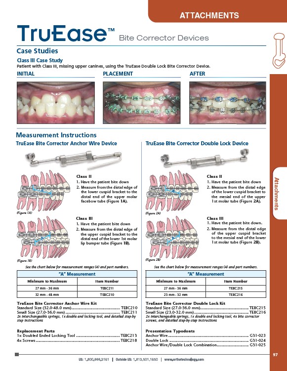
Class III Case Study
Patient with Class III, missing upper canines, using the TruEase Double Lock Bite Corrector Device.
INITIAL PLACEMENT AFTER
Measurement Instructions
TruEase Bite Corrector Anchor Wire Device TruEase Bite Corrector Double Lock Device
A
A
TruEase Bite Corrector Anchor Wire Kit
Standard Size (32.0-48.0 mm) ......................................... TEBC210
Small Size (27.0-36.0 mm) .............................................. TEBC211
2x interchangeable springs, 1x double end locking tool, and detailed step-by
step instructions
A
TruEase Bite Corrector Double Lock Kit
Standard Size (27.0-36.0 mm) ......................................... TEBC215
Small Size (23.0-32.0 mm) .............................................. TEBC216
2x interchangeable springs, 1x double end locking tool, 4x bite corrector
screws, and detailed step-by-step instructions
Replacement Parts
1x Doubled Ended Locking Tool ..................................... TEBC213
4x Screws ....................................................................... TEBC218
Presentation Typodonts
Anchor Wire .................................................................... G31-023
Double Lock ................................................................... G31-024
Anchor Wire/Double Lock Combination........................... G31-025
TruEase™
Case Studies
Bite Corrector Devices
Class II
1. Have the patient bite down
2. Measure from the distal edge of
the lower cuspid bracket to the
distal end of the upper molar
facebow tube (Figure 1A).
Class II
1. Have the patient bite down
2. Measure from the distal edge
of the lower cuspid bracket to
the mesial end of the upper
1st molar tube (Figure 2A).
Class III
1. Have the patient bite down
2. Measure from the distal edge of
the upper cuspid bracket to the
distal end of the lower 1st molar
lip bumper tube (Figure 1B).
Class III
1. Have the patient bite down.
2. Measure from the distal edge
of the upper cuspid bracket
to the mesial end of the lower
1st molar tube (Figure 2B).
“A” Measurement
Minimum to Maximum Item Number
27 mm - 36 mm TEBC211
32 mm - 48 mm TEBC210
“A” Measurement
Minimum to Maximum Item Number
27 mm - 36 mm TEBC215
23 mm - 32 mm TEBC216
(Figure 1A) (Figure 2A)
(Figure 1B) (Figure 2B)
See the chart below for measurement ranges (A) and part numbers. See the chart below for measurement ranges (A) and part numbers.
97
ATTACHMENTS
Attttaacchhmeennttss