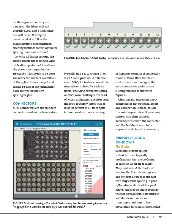
FIGURE 4: A 1x12 MPO that displays compliance to IEC specification 61300-3-35.
May/June 2019 I 49
on the v-grooves or they are
damaged, the fibers will not
properly align, and a high splice
loss will occur. It is highly
recommended to follow the
manufacturer’s recommended
cleaning methods so that optimum
splicing results are achieved.
As with all fusion splicers, the
ribbon splicer needs to have ARC
calibrations performed to calibrate
the power discharged by the
electrodes. This needs to be done
whenever the ambient conditions
of the splicer have changed and
should be part of the technician’s
daily routine before any
splicing begins.
CONNECTORS
MPO connectors are the standard
connectors used with ribbon cables,
typically in a 1 x 12 (Figure 4) or
2 x 12 configuration. A 108 fiber
count MPO, for instance, constitutes
nine ribbon splices for each 12
fibers. The MPO connectors bring
on their own challenges, the least
of which is cleaning. The fiber optic
industry routinely states that at
least 80 percent of all fiber optic
failures are due to not cleaning
or improper cleaning of connectors.
If one of those fiber ferrules is
contaminated or damaged, the
entire connector performance
is compromised as shown in
Figure 5.
Cleaning and inspecting MPO
connectors is not optional. Before
any connection is made, follow
this rule: inspect, clean if necessary,
inspect, and then connect.
Remember that both the connector
and the bulkhead need to be
inspected and cleaned as necessary.
RIBBON SPLICING
RUNDOWN
The Basics
Successful ribbon splicer
technicians are typically
professionals that are proficient
at splicing single fiber cables.
They understand the basics of
keeping the fiber, cleaver, splicer,
and stripper clean as is the case
with single fiber splicing. A good
splice always starts with a good
cleave, and a good cleave requires
that the optical fiber, fiber stripper,
and the cleaver are clean.
An important step in the
preparation for a mass fusion splice
Inspection
Manta 7777 Tip type: L Series
Anomalies detection MPO72-SM-PC
Auto Tune Image
Ready to measure step 1 of 2
Highlight fibers on live view
Name:
Result6
Folder: My Results
Customer:
Customer ID:
Inspect in Express Mode
Show Images
FAIL
Name: Result7
Fiber 1: FAIL
Fiber 2: FAIL
Fiber 3: FAIL
Fiber 4: FAIL
Fiber 5: FAIL
Fiber 6: FAIL
Fiber 7: FAIL
Fiber 8: FAIL
Fiber 9: FAIL
Fiber 10: FAIL
Fiber 11: FAIL
IL
Fiber 12: FAIL
Fiber 13: FAIL
Fiber 14: FAIL
ber Fiber 15: FAIL
FIGURE 5: Visual showing a 12 x 6 MPO with many ferrules not passing inspection.
Plugging fiber in would most certainly cause network failure(s).3