recommended that the equipment be spliced to the
existing multimode fibers to ensure that the modal
alignment between the cores of the optical fibers were
efficient. It should be noted that this type of technology
does not require specific equipment or the installation of
a splicing program. Modal adapting equipment, provided
in standard 1RU 19’’ rack, then became the new patch
panel for the upgraded multimode fibers. On the remote
site, no modal adapting equipment was needed. The
patch panel that the multimode fibers connect to was
preserved. The patch cords that connected the distribution
panel and the active equipment were simply replaced
by standard singlemode patch cord, since the transmission
over the multimode fiber was now approaching the
features and characteristics of singlemode fiber. The
transceivers usually use LC type connectors. Therefore,
singlemode LC/ST or LC/SC cords or any other necessary
connector type can be employed depending on the
project's specific multimode connectivity.
Upon transmission, the modal adapter served as
a perfect center launcher while acting as a perfect mode
filter on the receiver, retaining only the information
24 I ICT TODAY
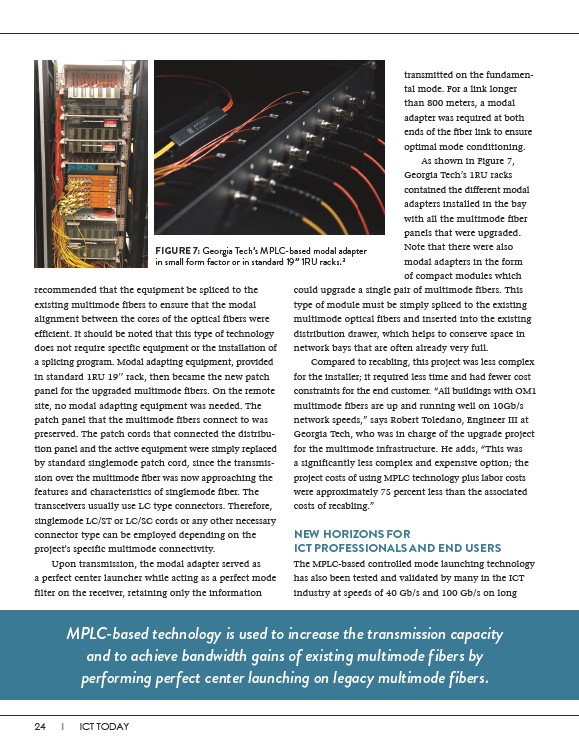
FIGURE 7: Georgia Tech’s MPLC-based modal adapter
in small form factor or in standard 19’’ 1RU racks.3
transmitted on the fundamental
mode. For a link longer
than 800 meters, a modal
adapter was required at both
ends of the fiber link to ensure
optimal mode conditioning.
As shown in Figure 7,
Georgia Tech’s 1RU racks
contained the different modal
adapters installed in the bay
with all the multimode fiber
panels that were upgraded.
Note that there were also
modal adapters in the form
of compact modules which
could upgrade a single pair of multimode fibers. This
type of module must be simply spliced to the existing
multimode optical fibers and inserted into the existing
distribution drawer, which helps to conserve space in
network bays that are often already very full.
Compared to recabling, this project was less complex
for the installer; it required less time and had fewer cost
constraints for the end customer. “All buildings with OM1
multimode fibers are up and running well on 10Gb/s
network speeds,” says Robert Toledano, Engineer III at
Georgia Tech, who was in charge of the upgrade project
for the multimode infrastructure. He adds, “This was
a significantly less complex and expensive option; the
project costs of using MPLC technology plus labor costs
were approximately 75 percent less than the associated
costs of recabling.”
NEW HORIZONS FOR
ICT PROFESSIONALS AND END USERS
The MPLC-based controlled mode launching technology
has also been tested and validated by many in the ICT
industry at speeds of 40 Gb/s and 100 Gb/s on long
MPLC-based technology is used to increase the transmission capacity
and to achieve bandwidth gains of existing multimode fibers by
performing perfect center launching on legacy multimode fibers.