Support: Cable Pathway and Wire Mesh Trays
Flexibility, particularly in installations with multiple
cable drops, is also important when planning the cable
pathway (Figure 6). In the case of runways, new designs
offer movable cross members that allow for maximum
flexibility. Radius drops can be placed exactly where
they are needed to path cable into or out of the vertical
manager. Additionally, easy-to-use tool-less pathway
dividers allow the user to maintain required space
between cable bundles within the pathway as dictated
by industry standards.
Another popular cable support solution is the wire
mesh cable tray, which can be supported from the wall,
ceiling, floor or from the tops of open racks. When looking
for wire mesh cable trays, look for designs featuring
smooth edges to protect cable and installers from getting
hurt, as well as zinc plating to allow electrical continuity
through splice connections.
Considerations for selecting a robust cable pathway
solution include:
1. Route
Will the cable pathway require irregular transitions or
simple turns? Look for tool-less and adjustable designs
that allow for ultimate flexibility in the pathway.
2. Support
The pathway should be able to support cables from
the ceiling, wall, racks or floor with adequate space
support away from sources of electromagnetic
interference (EMI).
3. Weight
Based on the size of runway and tray and distance
between supports, what is the maximum weight
supported? The support must be designed using
a 50 percent fill of cabling to allow for future growth.
4. Bonding and Safety
Consider designs with integrated bonding studs
to make installation easier. Is the bond appropriate
for the circuits carried per local electrical code?
Make sure the pathway is securely supported
and bonded.
62 I ICT TODAY
5. Accessibility
Is the pathway isolated from nontechnical staff but still
accessible for new cable runs?
6. Accessories
Each egress/ingress point should provide sufficient protection
for cables. This includes ensuring cables are properly
divided/organized within the runway or tray for
easy tracing.
7. Heat
NFPA-70 and TIA TSB-184-A also address heat buildup and
limit cable fill based on the types of circuits. PoE circuits
above 60 Watts (high-amperage power circuits) fall into
this category.
8. Corrosion Resistance
Is the pathway located where it will be exposed to
weather, chemicals or other environmental conditions
that require an additional layer of corrosion protection?
Consider a cost-effective corrosion-resistant finish with
resistance class IEC 61537 Class C8 that delivers corrosion
resistance almost equivalent to stainless steel.
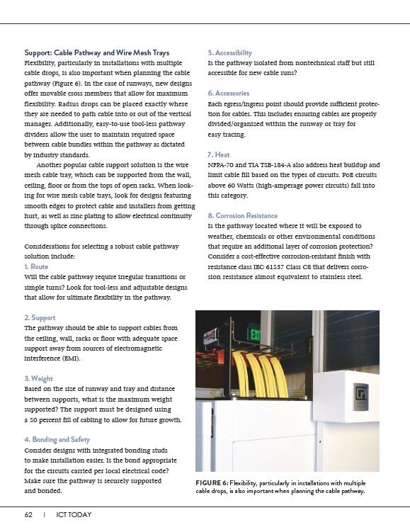
FIGURE 6: Flexibility, particularly in installations with multiple
cable drops, is also important when planning the cable pathway.