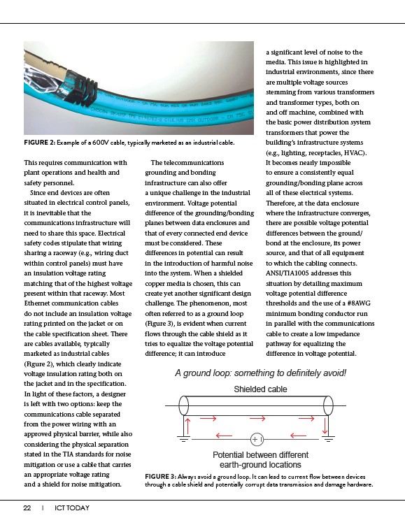
FIGURE 2: Example of a 600V cable, typically marketed as an industrial cable.
This requires communication with
plant operations and health and
safety personnel.
Since end devices are often
situated in electrical control panels,
it is inevitable that the
communications infrastructure will
need to share this space. Electrical
safety codes stipulate that wiring
sharing a raceway (e.g., wiring duct
within control panels) must have
an insulation voltage rating
matching that of the highest voltage
present within that raceway. Most
Ethernet communication cables
do not include an insulation voltage
rating printed on the jacket or on
the cable specification sheet. There
are cables available, typically
marketed as industrial cables
(Figure 2), which clearly indicate
voltage insulation rating both on
the jacket and in the specification.
In light of these factors, a designer
is left with two options: keep the
communications cable separated
from the power wiring with an
approved physical barrier, while also
considering the physical separation
stated in the TIA standards for noise
mitigation or use a cable that carries
an appropriate voltage rating
and a shield for noise mitigation.
22 I ICT TODAY
a significant level of noise to the
media. This issue is highlighted in
industrial environments, since there
are multiple voltage sources
stemming from various transformers
and transformer types, both on
and off machine, combined with
the basic power distribution system
transformers that power the
building’s infrastructure systems
(e.g., lighting, receptacles, HVAC).
It becomes nearly impossible
to ensure a consistently equal
grounding/bonding plane across
all of these electrical systems.
Therefore, at the data enclosure
where the infrastructure converges,
there are possible voltage potential
differences between the ground/
bond at the enclosure, its power
source, and that of all equipment
to which the cabling connects.
ANSI/TIA1005 addresses this
situation by detailing maximum
voltage potential difference
thresholds and the use of a #8AWG
minimum bonding conductor run
in parallel with the communications
cable to create a low impedance
pathway for equalizing the
difference in voltage potential.
The telecommunications
grounding and bonding
infrastructure can also offer
a unique challenge in the industrial
environment. Voltage potential
difference of the grounding/bonding
planes between data enclosures and
that of every connected end device
must be considered. These
differences in potential can result
in the introduction of harmful noise
into the system. When a shielded
copper media is chosen, this can
create yet another significant design
challenge. The phenomenon, most
often referred to as a ground loop
(Figure 3), is evident when current
flows through the cable shield as it
tries to equalize the voltage potential
difference; it can introduce
A ground loop: something to definitely avoid!
Shielded cable
Potential between different
earth-ground locations
FIGURE 3: Always avoid a ground loop. It can lead to current flow between devices
through a cable shield and potentially corrupt data transmission and damage hardware.