March/April 2019 I 53
Central Equipment Room
TWDM PON
OTDR
4x10 Gb/s
XGS PON 10 Gb/s
GPON 2.5 Gb/s
1.2 Gb/s
10 Gb/s
4x10 Gb/s
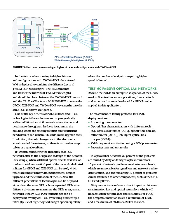
In the future, when moving to higher bitrates
and configurations with TWDM-PON, the external
WM is deployed to combine the different (up to 4)
TWDM-PON wavelengths. The WM combines
and isolates the individual TWDM wavelengths
and should be placed between the TWDM-PON line card
and the CE. The CE acts as a MUX/DEMUX to merge the
GPON, XGS-PON and TWDM-PON wavelengths into the
same PON as shown in Figure 5.
One of the key benefits of POL solutions and GPON
technologies is the evolution can happen gradually,
adding additional capabilities only where the network
needs more throughput. In those locations in the
building where the existing solution offers sufficient
bandwidth, it can remain. This minimizes upgrade costs.
In addition, the only changes are to the electronics
at each end of the network, so there is no need to swap
cables or upgrade cabling.
It is worth considering the flexibility that POL
networks offer to the design and redesign of the network.
For example, when sufficient optical fiber is available on
the horizontal and vertical part of the network, dedicated
splitters for GPON and XGS-PON can be used, which
results in simpler bandwidth management, simpler
upgrades and the elimination of the CE. Also, the
different generations of technologies can be deployed
either from the same OLT or from separated OLTs when
different divisions are managing the OLTs as segregated
networks. Finally, XGS-PON technologies can be
deployed in overlay of GPON even using different split
ratios (by use of higher optical budget optics) especially
ONT
OLT CEx
CEx = Coexistence Element (G.989.1)
WM = Wavelength Multiplexer (G.989.1)
WM
OTDR
FIGURE 5: Illustration when moving to higher bitrates and configurations with TWDM-PON.
when the number of endpoints requiring higher
speed is limited.
TESTING PASSIVE OPTICAL LAN NETWORKS
Because the POL is an enterprise adaptation of the GPON
used in fiber-to-the-home applications, the same tools
and expertise that were developed for GPON can be
applied in this application.
The recommended testing protocols for a POL
deployment are:
• Inspecting the connector
• Optical fiber characterization with different tools
(e.g., optical loss test set OLTS, optical time domain
reflectometer OTDR, intelligent optical link
mapper iOLM)
• Validating service activation using a PON power meter
• Reporting tests and test results
In optical fiber networks, 80 percent of the problems
are caused by dirty or damaged optical connectors,
10 percent of network problems are due to macrobends,
which are responsible for signal loss and network quality
deterioration, and the remaining 10 percent of problems
can be attributed to other components, such as the ONT,
OLT and splitters.
Dirty connectors can have a direct impact on bit error
rate, insertion loss and optical return loss, which will
impact system performance and reliability. For POLs,
the acceptable insertion loss is a minimum of 13 dB
and a maximum of 28 dB at a 20 km distance.