April/May/June 2020 I 13
ANSI/TIA-942-B specifies the LC connector for one or
two optical fibers and MPO for more than two fibers.
ISO/IEC 11801-5 and CENELEC EN 50173-5 specify the
same optical fiber connectors at the equipment outlet
and external network interface (LC and MPO). Unlike
TIA-942-B, they permit the use of other connectors that
meet the performance requirements of the standards
in other areas, such as in main, intermediate and zone
distributors as well as the local distribution point.
Another example is the use of course wavelength
division multiplexing (CWDM) or dense wavelength
division multiplexing (DWDM) within the data center.
Both have been used in the backhaul networks for years
and are often used in delivering connectivity to the data
center from the carrier’s network. Course wavelength
division multiplexing and DWDM allow for data to be
communicated through multiple wavelengths on the
same fiber, and then optical filtering is used to break
out into individual channels. The connectivity solution
roadmap needs to keep these in mind and provide longterm
support.
Fusion Splicing and Ribbon Fiber
Delivering the promise of tomorrow requires millions
of low loss connections. A single hyperscale data center
can easily contain over 100,000 servers and 500 to 1 million
connectors. This does not account for the number
of splices that could be in the order of tens of thousands.
If pre-terminated trunks are not being used, then the
number of splices can easily expand by an order of magnitude.
Dealing with tens to hundreds of thousands of
splices is no easy challenge. This level of splice density
can be equated to time-spent, making true the old adage
that “time equals money.”
Ribbon fiber, especially a flexible gel-free ribbon
product, can greatly help with this challenge. Mass fusion
splicing of no-gel ribbon has been shown to reduce the
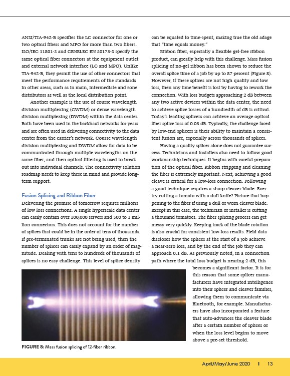
overall splice time of a job by up to 87 percent (Figure 8).
However, if these splices are not high quality and low
loss, then any time benefit is lost by having to rework the
connection. With loss budgets approaching 2 dB between
any two active devices within the data center, the need
to achieve splice losses of a hundredth of dB is critical.
Today’s leading splicers can achieve an average optical
fiber splice loss of 0.03 dB. Typically, the challenge faced
by low-end splicers is their ability to maintain a consistent
fusion arc, especially across thousands of splices.
Having a quality splicer alone does not guarantee success.
Technicians and installers also need to follow good
workmanship techniques. It begins with careful preparation
of the optical fiber. Ribbon stripping and cleaning
the fiber is extremely important. Next, achieving a good
cleave is critical for a low-loss connection. Following
a good technique requires a sharp cleaver blade. Ever
try cutting a tomato with a dull knife? Picture that happening
to the fiber if using a dull or worn cleaver blade.
Except in this case, the technician or installer is cutting
a thousand tomatoes. The fiber splicing process can get
messy very quickly. Keeping track of the blade rotation
is also crucial for consistent low-loss results. Field data
discloses how the splices at the start of a job achieve
a near-zero loss, and by the end of the job they can
approach 0.1 dB. As previously noted, in a connection
path where the total loss budget is nearing 2 dB, this
FIGURE 8: Mass fusion splicing of 12-fiber ribbon.
becomes a significant factor. It is for
this reason that some splicer manufacturers
have integrated intelligence
into their splicer and cleaver families,
allowing them to communicate via
Bluetooth, for example. Manufacturers
have also incorporated a feature
that auto-advances the cleaver blade
after a certain number of splices or
when the loss level begins to move
above a pre-set threshold.