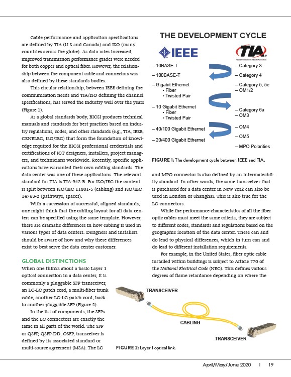
FIGURE 1: The development cycle between IEEE and TIA.
and MPO connector is also defined by an intermateability
standard. In other words, the same transceiver that
is purchased for a data center in New York can also be
used in London or Shanghai. This is also true for the
LC connectors.
While the performance characteristics of all the fiber
optic cables must meet the same criteria, they are subject
to different codes, standards and regulations based on the
geographic location of the data center. These can and
do lead to physical differences, which in turn can and
do lead to different installation requirements.
For example, in the United States, fiber optic cable
installed within buildings is subject to Article 770 of
the National Electrical Code (NEC). This defines various
degrees of flame retardance depending on where the
April/May/June 2020 I 19
Cable performance and application specifications
are defined by TIA (U.S and Canada) and ISO (many
countries across the globe). As data rates increased,
improved transmission performance grades were needed
for both copper and optical fiber. However, the relationship
between the component cable and connectors was
also defined by these standards bodies.
This circular relationship, between IEEE defining the
communication needs and TIA/ISO defining the channel
specifications, has served the industry well over the years
(Figure 1).
As a global standards body, BICSI produces technical
manuals and standards for best practices based on industry
regulations, codes, and other standards (e.g., TIA, IEEE,
CENELEC, ISO/IEC) that form the foundation of knowledge
required for the BICSI professional credentials and
certifications of ICT designers, installers, project managers,
and technicians worldwide. Recently, specific applications
have warranted their own cabling standards. The
data center was one of these applications. The relevant
standard for TIA is TIA-942-B. For ISO/IEC the content
is split between ISO/IEC 11801-5 (cabling) and ISO/IEC
14763-2 (pathways, spaces).
With a succession of successful, aligned standards,
one might think that the cabling layout for all data centers
can be specified using the same template. However,
there are dramatic differences in how cabling is used in
various types of data centers. Designers and installers
should be aware of how and why these differences
exist to best serve the data center customer.
THE DEVELOPMENT CYCLE
– 10BASE-T
– 100BASE-T
– Gigabit Ethernet
• Fiber
• Twisted Pair
– 10 Gigabit Ethernet
• Fiber
• Twisted Pair
– 40/100 Gigabit Ethernet
– 20/400 Gigabit Ethernet
– Category 3
– Category 4
– Category 5, 5e
– OM1/2
– Category 6a
– OM3
– OM4
– OM5
– MPO Polarities
TRANSCEIVER
FIGURE 2: Layer 1 optical link.
TRANSCEIVER
CABLING
GLOBAL DISTINCTIONS
When one thinks about a basic Layer 1
optical connection in a data center, it is
commonly a pluggable SFP transceiver,
an LC-LC patch cord, a multi-fiber trunk
cable, another LC-LC patch cord, back
to another pluggable SFP (Figure 2).
In the list of components, the SFPs
and the LC connectors are exactly the
same in all parts of the world. The SFP
or QSFP, QSFP-DD, OSFP, transceiver is
defined by its associated standard or
multi-source agreement (MSA). The LC