easily pulled through conduits and raceways and field
terminated. HDBaseT can carry AV and related signals
up to 328 feet (100 meters) over twisted pair. For longer
runs or where security or radio frequency interference
(RFI) are concerns, there are transmitter-receiver pairs
that work with optical fiber cable to carry the same
signals, minus power, over many miles. Here, the focus
is on HDBaseT over twisted pair.
Twisted-Pair Cable Construction
When running digital AV content over Category twisted-
pair cable, outside interference or alien crosstalk is a major
concern. The interference can come from nearby electrical
equipment, adjacent signal or power cables or from near-
by radio transmitters. Interference can cause bit errors
in the audio and video data streams, and it can corrupt
EDID, HDCP and control signal data transfers and handshakes.
The results range from image dropouts and flash-
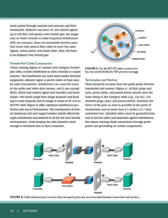
ing to audio dropouts and no image or sound at all. Cat 6A
SF/UTP cable (Figure 3) offers optimum interference pro-
tection and ease of termination. The combination of over-
all aluminum foil and copper braided shields effectively
repels interference encountered in all but the most hostile
environments, while keeping the cable diameter small
enough to terminate into an RJ45 connector.
Transmitter
Transmitter
12 I ICT TODAY
Pair
Conductor
Insulation
Outer Jacket
Foil Shield
Braided Shield
FIGURE 3: Cat 6A SF/UTP cable construction
has two overall shields for 100 percent coverage.
Termination and Patches
There should be no more than two patch points between
transmitter and receiver (Figure 4). All RJ45 plugs and
jacks, patch cables, and punch-downs should carry the
same rating as the Category cable (e.g., Cat 6A). Use
shielded plugs, jacks, and punch-downs. Maintain the
twists of the pairs as close as possible to the point of
termination and no more than 0.5 inches (12.7 mm)
untwisted wire. Shielded cables must be grounded from
end to end for safety and immunity against interference;
this means carrying shield connections through patch
points and grounding all system components.
2
1
Patch Cable Patch Cable
2
Wallplate Wallplate
1
Punch Block
Receiver
Receiver
Patch Cable
Wallplate
FIGURE 4: Cable infrastructure; no more than two patch points are recommended between transmitter and receiver.