50 I ICT TODAY
Width
Width
Width
Width
Rip Cord Width
Rip Cord
x2
Rip Cord
x2
Oversheath
Oversheath
2-Way
Oversheath
7-Way
4-Way
Rip Cord x2 Rip Cord x2
Oversheath
Oversheath
HDPE
MicroDuct x2
HDPE
MicroDuct x4
HDPE MicroDuct x7
HDPE MicroDuct x19 HDPE MicroDuct x24
Height
Height Height
24-Way
19-Way
NEW TECHNOLOGIES: BACKBONE,
IoT NETWORK, PoE, AND MORE
New technology was added and current technology was
evaluated—everything from equipping employees to
work from various environments to creating consistent
technology inside conference spaces.
The wireless network, which employees reported did
not always work, was also re-engineered. Wi-Fi coverage
was enhanced with three times the number of wireless
access points (WAPs) to eliminate areas without coverage.
The speed of the wireless network was dramatically
increased, support for the latest mobile devices was
added and a cellular DAS system was installed to ensure
coverage for cellular phone calls. ANSI/BICSI 006,
Distributed Antenna System (DAS) Design and Implementation
Best Practices provides valuable information for the design
and installation of a DAS system.
A major emphasis of the project was upgrading the
company’s technology infrastructure to enable mobile
computing and wireless operation of many work tools.
The core network backbone running up the building was
replaced with blown cable (also referred to as air-jetted
fiber) technology, and key networking equipment was
replaced to support the faster speeds required for a business
now heavily focused on advanced analytics.
GP’s old riser backbone, a mixture of singlemode and
multimode optical fiber deployed with armored jacketed
cables in innerduct, filled most of the available core space.
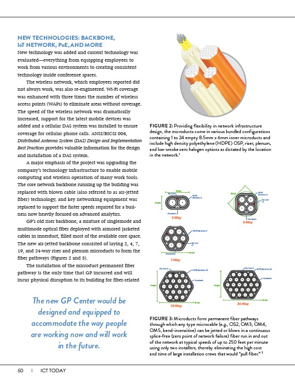
The new air-jetted backbone consisted of laying 2, 4, 7,
19, and 24-way riser and plenum microducts to form the
fiber pathways (Figures 2 and 3).
The installation of the microduct permanent fiber
pathway is the only time that GP incurred and will
incur physical disruption to its building for fiber-related
FIGURE 2: Providing flexibility in network infrastructure
design, the microducts come in various bundled configurations
containing 1 to 24 empty 8.5mm x 6mm inner microducts and
include high density polyethylene (HDPE) OSP, riser, plenum,
and low-smoke zero halogen options as dictated by the location
in the network.1
FIGURE 3: Microducts form permanent fiber pathways
through which any type microcable (e.g., OS2, OM3, OM4,
OM5, bend-insensitive) can be jetted or blown in a continuous
splice-free (zero point of network failure) fiber run in and out
of the network at typical speeds of up to 250 feet per minute
using only two installers, thereby eliminating the high cost
and time of large installation crews that would “pull fiber.” 2
The new GP Center would be
designed and equipped to
accommodate the way people
are working now and will work
in the future.