Insertion Loss (dB) at 100 MHz
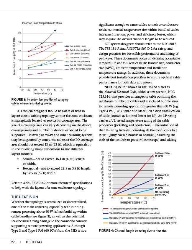
Insertion Loss Temperature Profiles
14
10 20 30 40 50 60 70
Temperature (��C)
26
24
22
20
18
16
22 I ICT TODAY
Cat 5e UTP Limit
Cat 5e Shielded Limit
Cat 5e UTP (24 AWG)
Cat 6 UTP (23 AWG)
Cat 6A UTP (23 AWG)
Cat 6A F/UTP (23 AWG)
Cat 7A S/FTP (22 AWG)
FIGURE 3: Insertion loss profiles of category
cables when transmitting power.
ICT system designers should be aware of how to
layout a zone cabling topology so that the zone enclosure
is strategically located to service its coverage area. The
size of a coverage area can vary depending on the device
coverage areas and number of devices expected to be
supported. However, as WAPs and other building systems
may be supported by zones, the radius of the EO coverage
area should not exceed 13 m (43 ft), which is equivalent
to the following shape dimensions in two different
layout formats:
• Square—not to exceed 18.4 m (60 ft) length
or width.
• Hexagonal—not to exceed 22.5 m (75 ft) length
by 19.5 m (65 ft) width.
Refer to ANSI/BICSI-007 or manufacturers’ specifications
to help with the layout of a zone enclosure topology.
THE HEAT IS ON
Whether the topology is centralized or decentralized,
one of the main concerns, especially with running
remote powering above 60 W, is heat build-up within
cable bundles (see Figure 3), as well as the potential
for electrical arcing damage to the connector contacts
supporting remote powering applications. Although
Type 3 and Type 4 PoE (60-90W from the PSE) is not
significant enough to cause cables to melt or conductors
to short, internal temperature rise within bundled cables
increases insertion, power and efficiency losses, which
may require the overall channel length to be reduced.
ICT system designers should refer to the NEC 2017,
TIA-TSB-184-A and ANSI/TIA-569-D-2 for safety and
design practices for best cable performance and sizing of
pathways. These documents focus on defining acceptable
temperature rise as it relates to the bundle size, conductor
size (AWG), ambient temperature and insulation
temperature ratings. In addition, these documents
provide best installation practices to ensure optimal cable
performance for both data and power.
NFPA 70, better known in the United States as
the National Electrical Code, added a new section, NEC
725.144, that provides an ampacity table outlining the
maximum number of cables and associated bundle sizes
for remote powering applications greater than 60 W (e.g.,
Type 4 PoE). NEC 2017 also identified a new classification
of cable, known as Limited Power (or LP). An LP rating
carries a UL-tested temperature rating of the cable
properties (jacketing and conductors). Determination of
the UL-rating includes powering all the conductors in a
large, tightly packed bundle in conduit (insulating the
ends of the conduit to prevent heat escape) and adding
Temperature (��C)
Subtract 18 m
at 60OC
Subtract 7 m
at 60OC
Subtract 3 m
at 60OC
No De-rating
up to 70OC
Insertion Loss Length De-Rating (m)
24
22
20
18
16
14
12
10
8
6
4
2
0
20 30 40 50 60 70
TIA-ISO/IEC Category 6A UTP (minimally compliant)
TIA-ISO/IEC Category 6A F/UTP (minimally compliant)
Category 6A UTP qualified for mechanical reliability up to 75��C (167��F)
Category 7A S/FTP qualified for mechanical reliability up to 75��C (167��F)
FIGURE 4: Channel length de-rating due to heat rise.