The best guidance currently available for testing
MPOs is the IEC technical report, 61282-15. Like a TSB
within TIA, technical reports offer guidance but not
requirements. Within the IEC’s SC 86C Working Group
1, there is work being done on an MPO testing standard
that would be published as 61280-4-5. That document
will likely be out in about a year. TIA’s TR-42.11
committee is working on an addendum to the 568.3-D
standard that references the IEC technical report within
the ANSI standards.
WHAT TO TEST
When looking inside standards for link and channel
testing, both ANSI/TIA and ISO/IEC specify two tiers
of certification. Within the TIA standards, this is Tier
1 and Tier 2 testing; within ISO/IEC, it is called basic
and extended. Tier 1 (basic) is required. It tests loss,
length and polarity of a fiber optic system. These are
the tests that cabling vendors must submit for warranty
coverage. Tier 2 (extended) is optional. It is done
with an optical time domain reflectometer (OTDR)
that provides information about each connection,
splice and cable segment
in the link and offers a
graphical representation
of the components and
their performance. Some
companies may choose to
extend Tier 1 tests with an
OTDR test, but only Tier 1
testing is required.
Fiber end face inspection
and certification is defined in the IEC 61300-3-35
standard. It has always been important that fiber end
faces are in pristine condition prior to mating, but
with MPO connections, it becomes critically important
because there are multiple fibers in a single connector,
and contamination on the end face has a much greater
impact. Ensuring a clean connector for all 8, 12 or 24
fibers on an MPO end face is more challenging than for
a typical LC or SC, especially when considering that a
singlemode fiber has a core only 9 microns in diameter
and a multimode fiber only 50 microns.
Since the surface area of the MPO connector is larger,
44 I ICT TODAY
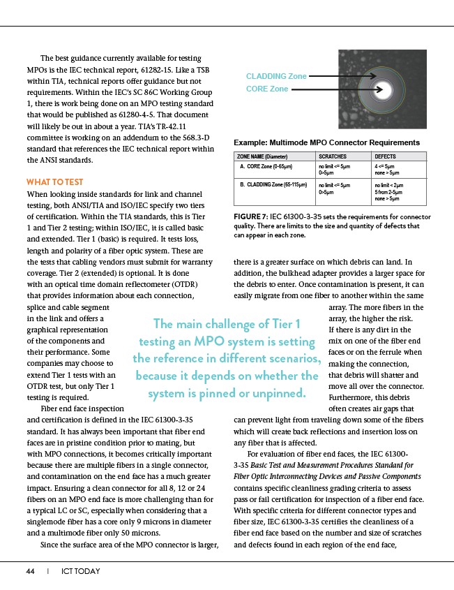
CLADDING Zone
CORE Zone
Example: Multimode MPO Connector Requirements
ZONE NAME (Diameter)
SCRATCHES DEFECTS
no limit <= 5μm
0>5μm
4 <= 5μm
none > 5μm
no limit <= 5μm
0>5μm
no limit < 2μm
5 from 2-5μm
none > 5μm
A. CORE Zone (0-65μm)
B. CLADDING Zone (65-115μm)
FIGURE 7: IEC 61300-3-35 sets the requirements for connector
quality. There are limits to the size and quantity of defects that
can appear in each zone.
there is a greater surface on which debris can land. In
addition, the bulkhead adapter provides a larger space for
the debris to enter. Once contamination is present, it can
easily migrate from one fiber to another within the same
array. The more fibers in the
array, the higher the risk.
If there is any dirt in the
mix on one of the fiber end
faces or on the ferrule when
making the connection,
that debris will shatter and
move all over the connector.
Furthermore, this debris
often creates air gaps that
The main challenge of Tier 1
testing an MPO system is setting
the reference in different scenarios,
because it depends on whether the
system is pinned or unpinned.
can prevent light from traveling down some of the fibers
which will create back reflections and insertion loss on
any fiber that is affected.
For evaluation of fiber end faces, the IEC 61300-
3-35 Basic Test and Measurement Procedures Standard for
Fiber Optic Interconnecting Devices and Passive Components
contains specific cleanliness grading criteria to assess
pass or fail certification for inspection of a fiber end face.
With specific criteria for different connector types and
fiber size, IEC 61300-3-35 certifies the cleanliness of a
fiber end face based on the number and size of scratches
and defects found in each region of the end face,