• SFP to SFP connectivity: Over multimode fiber (without
SWDM technology), this will support up to 10 Gb/s.
In a classic architecture, there is an MPO trunk cable
between two cassettes; the cassettes break down to
LCs, and the LCs connect to a switch at one end and
a server at the other, or a switch at both ends. In
this case, always inspect the MPO connection to the
cassettes, both inside the cassette and the trunk cable
itself. The loss, length and polarity test can be done
at the duplex LC drops with a normal, duplex optical
loss test set (OLTS). With pre-assembled cables that
go in and out of the trunk, it is not usually necessary
to conduct a loss, length and polarity test of that
trunk unless it has been damaged during installation.
If that is the case, it will be discovered when testing
the LC drops. The technician may need to conduct a
troubleshooting event to find the fault.
46 I ICT TODAY
MPO connections; then use an MPO tester to test
those links or channels. Finally, do a quick auto test
of all 12 fibers for loss, length and polarity at the
same time.
As emphasized earlier, inspecting the fiber end faces
is critical. MPO is particularly prone to collecting debris
that can cross-contaminate, possibly cause damage, and
certainly affect the performance of the system, which has
a much lower loss requirement than previous systems. So
inspect the fiber end face before connecting. Check to see
if they are clean or run an automated pass/fail analysis
with the test equipment. If it is dirty, clean it. Inspect
again; ask if it is clean. Connect only when it is
absolutely clean.
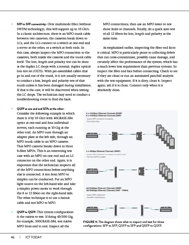
FIGURE 9: This diagram shows what to inspect and test for three
configurations: SFP to SFP, QSFP to SFP and QSFP to QSFP.
• QSFP at one end and SFPs at the other:
Consider the following example in which
there is 4 by 10 Gb/s with 40GBASE-SR4
optics at one end and four individual
servers, each running at 10 Gig at the
other end. An MPO runs through an
adapter plate at the left side, through an
MPO trunk cable to an MPO cassette.
That MPO cassette breaks down to three
8-fiber MPOs. This is an interesting test
case with an MPO on one end and an LC
connector on the other end. Again, it is
important that the technician inspects all
of the MPO connections before anything
else is connected. A test from MPO to
simplex can be conducted. Put an MPO
light source on the left-hand side and take
a simplex power meter to work through
the 8 or 12 fibers on the right-hand side.
The other technique is to use a fanout
cable and test MPO to MPO.
• QSFP to QSFP: This system configuration
is the easiest to test. If doing 40/100 Gig,
for example, 100GBASE-SR4, test native
MPO from end to end. Inspect all the