These two broadly classified
architectures have opposing
effects on the cost of cabling and
connectivity required. The parallel
optics based architecture requires
multiple fibers for transmit and
receive directions, thus needing
multi-fiber push on connectors
(MPOs). The WDM architectures
are relatively simpler from a cabling
and connectivity perspective, since
they only need two fibers and
rely on duplex-LC connectors for
typical data center installations. By
comparing these two architectures
with respect to their power budget,
total cost of ownership (where the
cost of cable, connectivity, and
transceiver is considered), and the
cost of a link in terms of $/Gb/s,
ICT designers, installers, and project
managers can gain valuable insight
into the cost of deploying 100 Gb
and 400 Gb links—vital information
for choosing the right optical fiber
architecture based on the end-user’s
migration plans.
52 I ICT TODAY
OPTICAL FIBER
ARCHITECTURES
When considering the 4-lane parallel
singlemode fiber-based architecture,
a PSM4 based device is used; each
of the four lower speed electrical
signals modulate the intensity of
a laser, typically emitting around
1300 nm. In a PSM4 device, all four
lasers operate at the same center
wavelength and, consequently, do
not have wavelength diversity. The
four optical channels are carrying
over independent fiber paths and
are multiplexed into a 12-fiber MPO
connector. On the receive end,
four receive optical fibers carry the
optical signals from the other end
of the link and are converted back
to electrical signals in the optical
receiver unit.
Devices based on CWDM4
technology for the 4-lane coarse
wavelength division multiplexing
architecture have lasers operating
at different wavelengths. These
modulated optical signals with
In a PSM4 device,
all four lasers
operate at the same
center wavelength
and, consequently,
do not have
wavelength diversity.
wavelength diversity are multiplexed
into a single optical fiber using a
multiplexer. At the receive end,
the multiple optical channels
received are de-multiplexed using a
de-multiplexer and then converted
back to their native electrical format.
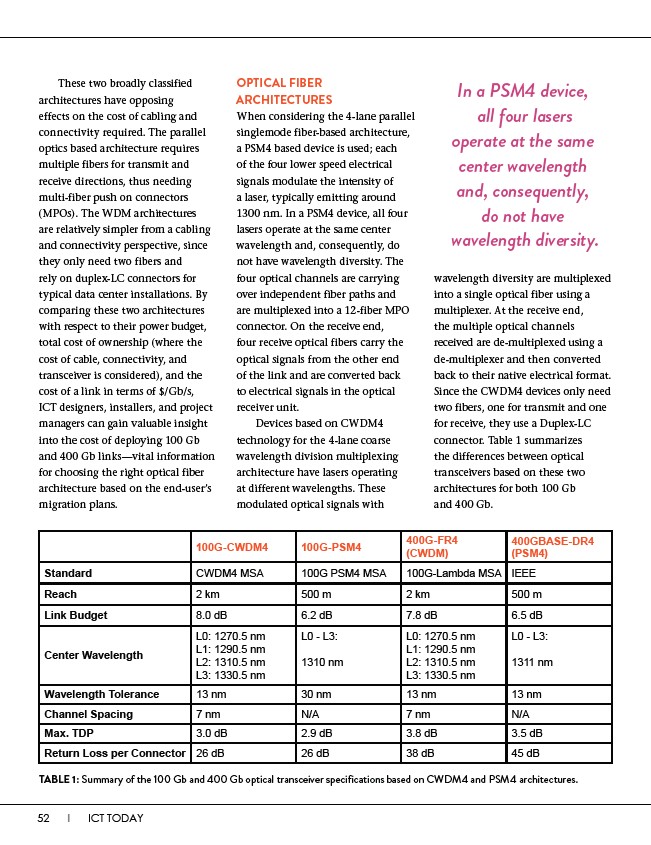
Since the CWDM4 devices only need
two fibers, one for transmit and one
for receive, they use a Duplex-LC
connector. Table 1 summarizes
the differences between optical
transceivers based on these two
architectures for both 100 Gb
and 400 Gb.
100G-CWDM4 100G-PSM4 400G-FR4
(CWDM)
400GBASE-DR4
(PSM4)
Standard CWDM4 MSA 100G PSM4 MSA 100G-Lambda MSA IEEE
Reach 2 km 500 m 2 km 500 m
Link Budget 8.0 dB 6.2 dB 7.8 dB 6.5 dB
Center Wavelength
L0: 1270.5 nm
L1: 1290.5 nm
L2: 1310.5 nm
L3: 1330.5 nm
L0 - L3:
1310 nm
L0: 1270.5 nm
L1: 1290.5 nm
L2: 1310.5 nm
L3: 1330.5 nm
L0 - L3:
1311 nm
Wavelength Tolerance 13 nm 30 nm 13 nm 13 nm
Channel Spacing 7 nm N/A 7 nm N/A
Max. TDP 3.0 dB 2.9 dB 3.8 dB 3.5 dB
Return Loss per Connector 26 dB 26 dB 38 dB 45 dB
TABLE 1: Summary of the 100 Gb and 400 Gb optical transceiver specifications based on CWDM4 and PSM4 architectures.