January/February 2019 I������53
350%
300%
250%
200%
150%
100%
0%
100G-CWDM4
$ (Relative to 100G-CWDM4)
Transceiver Relative Sale Price
100G-PSM4 400G-FR4 400GBASE-DR4
50%
$/Gb/s (Relative to 100G-CWDM4)
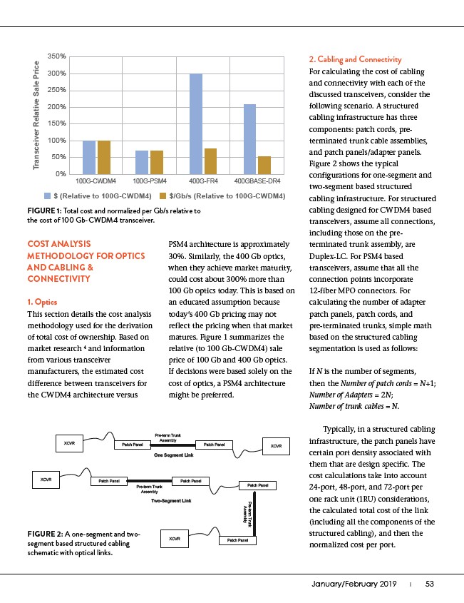
FIGURE 1: Total cost and normalized per Gb/s relative to
the cost of 100 Gb-CWDM4 transceiver.
COST ANALYSIS
METHODOLOGY FOR OPTICS
AND CABLING &
CONNECTIVITY
1. Optics
This section details the cost analysis
methodology used for the derivation
of total cost of ownership. Based on
market research 4 and information
from various transceiver
manufacturers, the estimated cost
difference between transceivers for
the CWDM4 architecture versus
XCVR Patch Panel
Pre-term Trunk
Assembly
Patch Panel XCVR
XCVR Patch Panel
One Segment Link
Pre-term Trunk
Assembly
Patch Panel
Patch Panel
Pre-term Trunk
Assembly
Two-Segment Link
XCVR Patch Panel
FIGURE 2: A one-segment and twosegment
based structured cabling
schematic with optical links.
PSM4 architecture is approximately
30%. Similarly, the 400 Gb optics,
when they achieve market maturity,
could cost about 300% more than
100 Gb optics today. This is based on
an educated assumption because
today’s 400 Gb pricing may not
reflect the pricing when that market
matures. Figure 1 summarizes the
relative (to 100 Gb-CWDM4) sale
price of 100 Gb and 400 Gb optics.
If decisions were based solely on the
cost of optics, a PSM4 architecture
might be preferred.
2. Cabling and Connectivity
For calculating the cost of cabling
and connectivity with each of the
discussed transceivers, consider the
following scenario. A structured
cabling infrastructure has three
components: patch cords, preterminated
trunk cable assemblies,
and patch panels/adapter panels.
Figure 2 shows the typical
configurations for one-segment and
two-segment based structured
cabling infrastructure. For structured
cabling designed for CWDM4 based
transceivers, assume all connections,
including those on the preterminated
trunk assembly, are
Duplex-LC. For PSM4 based
transceivers, assume that all the
connection points incorporate
12-fiber MPO connectors. For
calculating the number of adapter
patch panels, patch cords, and
pre-terminated trunks, simple math
based on the structured cabling
segmentation is used as follows:
If N is the number of segments,
then the Number of patch cords = N+1;
Number of Adapters = 2N;
Number of trunk cables = N.
Typically, in a structured cabling
infrastructure, the patch panels have
certain port density associated with
them that are design specific. The
cost calculations take into account
24-port, 48-port, and 72-port per
one rack unit (1RU) considerations,
the calculated total cost of the link
(including all the components of the
structured cabling), and then the
normalized cost per port.