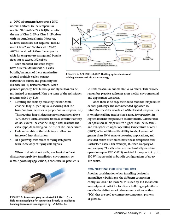
FIGURE 5: ANSI/BICSI-007: Building system horizontal
cabling elements within a star topology.
January/February 2019 I������23
a +20°C adjustment factor over a 25°C
normal ambient to the temperature
results. NEC Article 725.144(B) permits
the use of Class 2-LP or Class 3-LP cables
with no bundle size limits. However,
LP-rated cables are not required; non-LP
rated Class 2 and 3 cables with 22-26
AWG sizes should follow the ampacity
table for temperature ratings and bundle
sizes not to exceed 192 cables.
Each standard and code might
have different definitions of a cable
bundle, but most of them standardize
around multiple cables, contact
between the cables and proximity (or
distance limits) between cables. When
to limit maximum bundle size to 24 cables. This easy-toremember
practice addresses most media, environmental
and application scenarios.
Since there is no easy method to monitor temperature
or cool pathways, the recommended approach to
minimize the risks associated with elevated temperatures
is to select cabling media that is rated for operation in
higher ambient temperature environments. Cables rated
for operation at temperatures higher than the ISO/IEC
and TIA specified upper operating temperature of 60°C
(140°F) offer additional flexibility for deployment of
greater than 60 W remote powering applications, and
shielded cables offer much better heat dissipation over
unshielded cables. For example, shielded category 6A
and category 7A cables that are mechanically rated for
operation up to 75°C (167°F) are ideal for support of up to
100 W (1A per pair) in bundle configurations of up to
192 cables.
CONNECTING OUTSIDE THE BOX
Another consideration when installing devices in
an intelligent building is the different connection
configurations. The term “EO” is used by TIA to indicate
an equipment outlet for facility or building applications
outside the definition of telecommunications outlets
(TOs) that are used to connect to computers, printers
or phones.
planned properly, heat build-up and signal loss can be
minimized or mitigated. Here are some of the techniques
recommended by TIA:
• Derating the cable by reducing the horizontal
channel length. (See Figure 4 showing that the
insertion loss increases in proportion to temperature.)
This requires length derating at temperatures above
40°C (68°F). Installers need to make certain that they
do not exceed the channel length that matches the
cable type, depending on the rise of the temperature.
• Unbundle cable in the cable tray to allow for
improved heat dissipation.
• In a pathway, mix cables carrying PoE power
with those only carrying data signals.
When in doubt about cable, mechanical or heat
dissipation capability, installation environment, or
remote powering application, a conservative practice is
FIGURE 6: A modular plug terminated link (MPTL) is a
field-terminated plug for connecting directly to intelligent
building devices and is recognized by TIA-568.2-D.