in the system. It will pass or fail
based on the polarity of the system
that it tests.
TIER ONE TESTING
The main challenge of Tier 1 testing an
MPO system is setting the reference in
different scenarios, because it depends
on whether the system is pinned or
unpinned. If using a test set that has
pinned ports, use an unpinned to
unpinned test cord to do a one cord
reference. One cord reference, which
is one cord between the transmitters
and the receiver, is the recommended
reference for testing links. If the test set
is pinned, use an unpinned to unpinned
test cord to reference it. The technician
cannot verify the reference without
adding a third cord. When adding
in the receive cord, which would be
unpinned to unpinned, a pinned system
can be tested.
The standards recommend that the
records are verified after a reference
is set. This is done by connecting the
launch cord and receive cord through a high-quality
coupler or adapter. Then, do an auto test and confirm
that the loss is below a specific value; the loss value
depends on whether singlemode or multimode fiber is
being used. This cannot be done with MPO, because if
there are two unpinned to unpinned cords, they cannot
be connected together. What is needed is a third cord
that is pinned to pinned and two adapters. This results in
a higher loss. To address this issue, there are some MPO
connectors available on the market today that allow pins
to be either retracted, or removed, and then reinstalled.
These connectors can help with test cord issues and solve
some of the pinned to unpinned challenges.
The easiest way to test MPO with an end-to-end
link or channel is by using a dedicated MPO tester with
MPO ports. This has an MPO source at one end and an
MPO power meter at the other end. Start by setting the
reference and ensure the use of the correct pinned or
48 I ICT TODAY
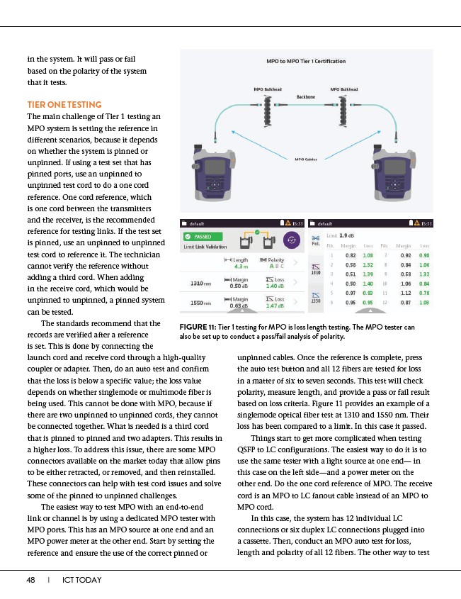
FIGURE 11: Tier 1 testing for MPO is loss length testing. The MPO tester can
also be set up to conduct a pass/fail analysis of polarity.
unpinned cables. Once the reference is complete, press
the auto test button and all 12 fibers are tested for loss
in a matter of six to seven seconds. This test will check
polarity, measure length, and provide a pass or fail result
based on loss criteria. Figure 11 provides an example of a
singlemode optical fiber test at 1310 and 1550 nm. Their
loss has been compared to a limit. In this case it passed.
Things start to get more complicated when testing
QSFP to LC configurations. The easiest way to do it is to
use the same tester with a light source at one end— in
this case on the left side—and a power meter on the
other end. Do the one cord reference of MPO. The receive
cord is an MPO to LC fanout cable instead of an MPO to
MPO cord.
In this case, the system has 12 individual LC
connections or six duplex LC connections plugged into
a cassette. Then, conduct an MPO auto test for loss,
length and polarity of all 12 fibers. The other way to test