FIGURE 13: Tier 2 testing of an MPO characterizes individual
events, making it an excellent trouble shooting tool.
January/February 2019 I������49
Testing 24f Systems with 12f Tester
• Trunks alone do not need to be tested for loss/strength
- Test links or channels instead (typically 12f or LC)
������������������������������������������������������������������ �� ��
MPO Bulkhead
Trunk
2x12f to 24f
MPO Test Cords
MPO Bulkhead
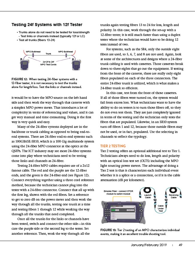
FIGURE 12: When testing 24-fiber systems with a
12-fiber tester, it is not necessary to test the trunks
alone for length/loss. Test the links or channels instead.
it would be to have the MPO source on the left hand
side and then work the way through that cassette with
a simplex MPO power meter. That introduces a lot of
complexity in terms of referencing and values, and it can
get very manual and time consuming. Doing it the first
way is very quick and easy.
Many of the 24-fiber systems deployed are in the
backbone or trunk cabling as opposed to being end-toend
systems. There are 24-fiber end-to-end systems such
as 100GBASE-SR10, which is a 100 Gig multimode system
using the 24-fiber MPO connector at the optics at the
QSFPs. The ICT industry may see more 24-fiber systems
come into play where technicians need to be testing
those links and channels as 24-fiber.
Testing 24-fiber MPO cables requires use of a 2x12
fanout cable. The red and the purple are the 12-fiber
ends, and the green is the 24-fiber end (see Figure 12).
Connect everything together using a three cord reference
method, because the technician cannot plug into the
tester with a 24-fiber connector. Connect that all up with
the first leg, shown with the red fibers. Set a reference
to get to zero dB on the power meter and then work the
way through all the trunks, testing one trunk at a time
and testing fibers 1 through 12 while working the way
through all the trunks that need completed.
Once all the trunks for the links or channels have
been tested, switch and connect the other side—in this
case the purple side or the second leg to the tester. Set
another reference. Then, work the way through all the
trunks again testing fibers 13 to 24 for loss, length and
polarity. In this case, work through the set-up with a
12-fiber tester; it is still much faster than using a duplex
tester where the technician would have to be doing 12
tests instead of two.
For systems, such as the SR4, only the outside eight
fibers are used, so 5, 6, 7, and 8 are not used. Again, look
at some of the architectures and designs where a 24-fiber
trunk cabling is used with cassettes. Those cassettes break
down to three eights that go out the equipment. If testing
from the front of the cassette, there are really only eight
fibers populated on each of the three connectors. The
entire 24-fiber trunk is utilized, which is what makes a
24-fiber trunk so efficient.
In this case, test from the front of those cassettes.
If all of those fibers were turned on, the system would
fail from excess loss. What technicians want to have the
ability to do on testers is to turn those fibers off, so they
do not even test them. They are just completely ignored
in terms of the testing and the technician only tests the
fibers that are populated. Likewise, in an SR10 system
turn off fibers 1 and 12, because those outside fibers may
not be used, or in fact, populated. Use the selecting in
channels to reflect the typology.
TIER 2 TESTING
Tier 2 testing offers an optional additional test to Tier 1.
Technicians always need to do loss, length and polarity
with an optical loss test set (OLTS) including the MPO
light sourcing power meters. The advantage of doing a
Tier 2 test is that it characterizes each individual event
whether it is a splice or a connection, or if it is the cable
attenuation (dB per kilometer).
Simplex Fiber - connect OTDR
module to switch module Launch
Cable
Receiving
Cable
Cable
Under
Test