January/February 2019 I������45
including the core, cladding, adhesive layer and contact
zones. With MPO connectors, only two zones matter:
the core and the cladding (see Figure 7).
Proactive fiber inspection is essential before
connecting any fibers. If the end faces are not dirty, then
they can be connected. If there is any dirt, clean it and
then inspect it again to make sure the cleaning process
was effective. A common mistake is cleaning before
inspecting the fiber, but there is no point in cleaning
something that is already clean, and that fiber end face
should not be touched more than necessary.
Cleaning MPO connectors can be a challenge. There
are specific tools on the market to do it. The one click
cleaners have become popular over the last several years.
They are easy to use, because they can clean inside of a
bulkhead as well as the fiber end face itself. The cleaning
tape these devices use is broad enough to go across the
entire fiber end face and allows the pins to go on either
side of the tape.
When considering whether to use wet or dry cleaning
methods, note that MPO ferrules are exceedingly prone
to static buildup, which means that any kind of dust
gravitates right to the fiber end face. A lot of the wet
cleaning solutions remove some of the static discharge,
which makes it a good idea for MPO connectors.
To ensure that the system is free of contamination,
both sides of every connection must be clean. Patch cords
are easy to access and view compared to the fiber inside
the bulkhead, which is frequently overlooked because
typically the installer does not have the right tool.
However, it is a mistake to skip it. The bulkhead side may
only be half of the connection, but it is far more likely to
be dirty and problematic.
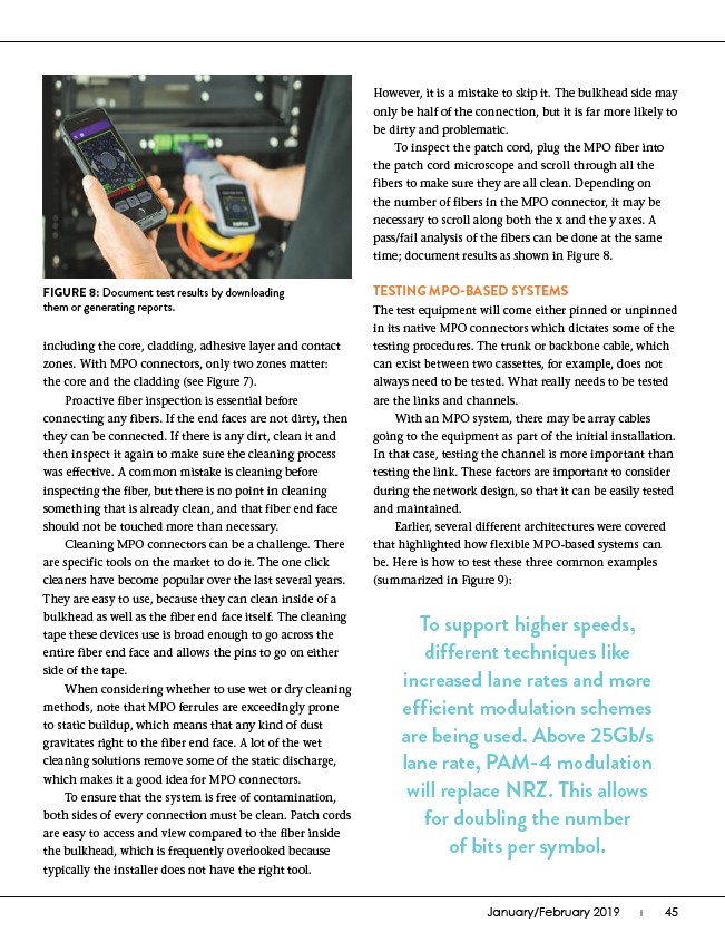
To inspect the patch cord, plug the MPO fiber into
the patch cord microscope and scroll through all the
fibers to make sure they are all clean. Depending on
the number of fibers in the MPO connector, it may be
necessary to scroll along both the x and the y axes. A
pass/fail analysis of the fibers can be done at the same
time; document results as shown in Figure 8.
TESTING MPO-BASED SYSTEMS
The test equipment will come either pinned or unpinned
in its native MPO connectors which dictates some of the
testing procedures. The trunk or backbone cable, which
can exist between two cassettes, for example, does not
always need to be tested. What really needs to be tested
are the links and channels.
With an MPO system, there may be array cables
going to the equipment as part of the initial installation.
In that case, testing the channel is more important than
testing the link. These factors are important to consider
during the network design, so that it can be easily tested
and maintained.
Earlier, several different architectures were covered
that highlighted how flexible MPO-based systems can
be. Here is how to test these three common examples
(summarized in Figure 9):
FIGURE 8: Document test results by downloading
them or generating reports.
To support higher speeds,
different techniques like
increased lane rates and more
efficient modulation schemes
are being used. Above 25Gb/s
lane rate, PAM-4 modulation
will replace NRZ. This allows
for doubling the number
of bits per symbol.