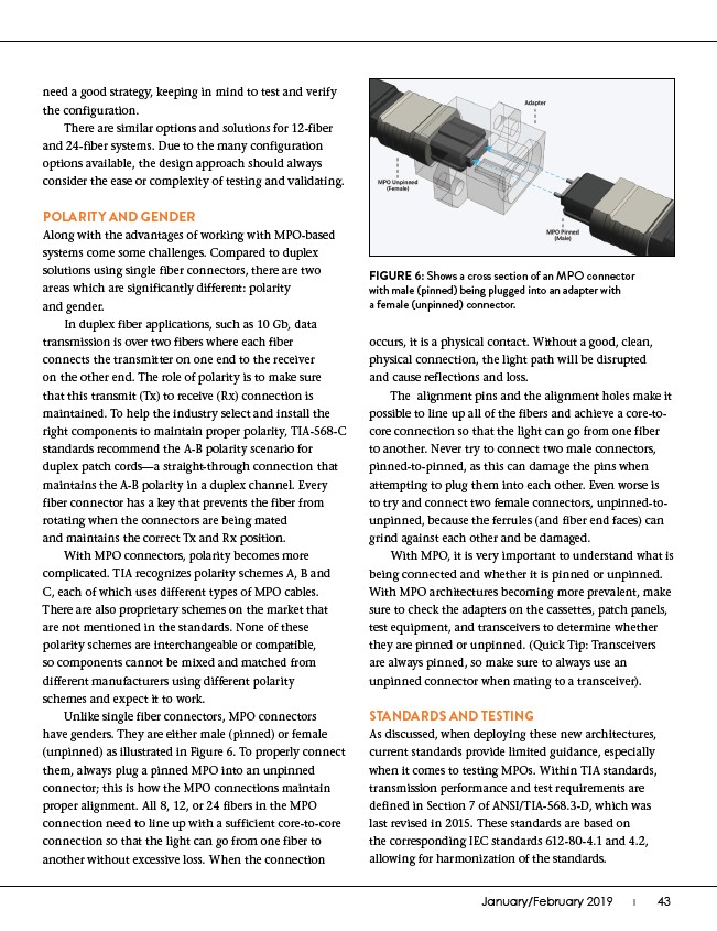
FIGURE 6: Shows a cross section of an MPO connector
with male (pinned) being plugged into an adapter with
a female (unpinned) connector.
January/February 2019 I������43
need a good strategy, keeping in mind to test and verify
the configuration.
There are similar options and solutions for 12-fiber
and 24-fiber systems. Due to the many configuration
options available, the design approach should always
consider the ease or complexity of testing and validating.
POLARITY AND GENDER
Along with the advantages of working with MPO-based
systems come some challenges. Compared to duplex
solutions using single fiber connectors, there are two
areas which are significantly different: polarity
and gender.
In duplex fiber applications, such as 10 Gb, data
transmission is over two fibers where each fiber
connects the transmitter on one end to the receiver
on the other end. The role of polarity is to make sure
that this transmit (Tx) to receive (Rx) connection is
maintained. To help the industry select and install the
right components to maintain proper polarity, TIA-568-C
standards recommend the A-B polarity scenario for
duplex patch cords—a straight-through connection that
maintains the A-B polarity in a duplex channel. Every
fiber connector has a key that prevents the fiber from
rotating when the connectors are being mated
and maintains the correct Tx and Rx position.
With MPO connectors, polarity becomes more
complicated. TIA recognizes polarity schemes A, B and
C, each of which uses different types of MPO cables.
There are also proprietary schemes on the market that
are not mentioned in the standards. None of these
polarity schemes are interchangeable or compatible,
so components cannot be mixed and matched from
different manufacturers using different polarity
schemes and expect it to work.
Unlike single fiber connectors, MPO connectors
have genders. They are either male (pinned) or female
(unpinned) as illustrated in Figure 6. To properly connect
them, always plug a pinned MPO into an unpinned
connector; this is how the MPO connections maintain
proper alignment. All 8, 12, or 24 fibers in the MPO
connection need to line up with a sufficient core-to-core
connection so that the light can go from one fiber to
another without excessive loss. When the connection
occurs, it is a physical contact. Without a good, clean,
physical connection, the light path will be disrupted
and cause reflections and loss.
The alignment pins and the alignment holes make it
possible to line up all of the fibers and achieve a core-tocore
connection so that the light can go from one fiber
to another. Never try to connect two male connectors,
pinned-to-pinned, as this can damage the pins when
attempting to plug them into each other. Even worse is
to try and connect two female connectors, unpinned-tounpinned,
because the ferrules (and fiber end faces) can
grind against each other and be damaged.
With MPO, it is very important to understand what is
being connected and whether it is pinned or unpinned.
With MPO architectures becoming more prevalent, make
sure to check the adapters on the cassettes, patch panels,
test equipment, and transceivers to determine whether
they are pinned or unpinned. (Quick Tip: Transceivers
are always pinned, so make sure to always use an
unpinned connector when mating to a transceiver).
STANDARDS AND TESTING
As discussed, when deploying these new architectures,
current standards provide limited guidance, especially
when it comes to testing MPOs. Within TIA standards,
transmission performance and test requirements are
defined in Section 7 of ANSI/TIA-568.3-D, which was
last revised in 2015. These standards are based on
the corresponding IEC standards 612-80-4.1 and 4.2,
allowing for harmonization of the standards.